SPI是一种非常常用的串行通讯协议,今天我们过一遍如何在Linux下试下SPI驱动的编写,并且借助一个IC来实现ARM主机通过SPI和外设之间进行数据交互。
Linux下的SPI框架
SPI在Linux中也是以一种Bus呈现出来的。和前面我们做的Platform总线一样,只不过platform是一种虚拟的总线而SPI是一种实际的总线。在内核中,如果要实现SPI协议来进行数据传输,是要通过SPI的主机控制器驱动和另一个设备驱动。回顾一下我们前面写的SPI裸机驱动(好像还没发布),是有一个bsp_spi.c(.h)还有个icm20806.c。前面的bsp_spi就相当于主机控制器驱动,所有的SPI外设都要通过这个主机控制器驱动去和我们的SOC进行通讯,而后面的icm20806.c就是设备驱动,每个SPI外设就对应一个单独的设备驱动。不管是什么SPI设备,主机驱动应该都是一样的,我们要做的就是各个外设的SPI设备驱动。
SPI主机驱动
SPI的主机驱动正常来说都是由半导体厂商直接提供给我们的,是由一个结构体spi_master来描述的(include/linux/spi/spi.h)。


  1 /**
  2  * struct spi_master - interface to SPI master controller
  3  * @dev: device interface to this driver
  4  * @list: link with the global spi_master list
  5  * @bus_num: board-specific (and often SOC-specific) identifier for a
  6  *    given SPI controller.
  7  * @num_chipselect: chipselects are used to distinguish individual
  8  *    SPI slaves, and are numbered from zero to num_chipselects.
  9  *    each slave has a chipselect signal, but it's common that not
 10  *    every chipselect is connected to a slave.
 11  * @dma_alignment: SPI controller constraint on DMA buffers alignment.
 12  * @mode_bits: flags understood by this controller driver
 13  * @bits_per_word_mask: A mask indicating which values of bits_per_word are
 14  *    supported by the driver. Bit n indicates that a bits_per_word n+1 is
 15  *    supported. If set, the SPI core will reject any transfer with an
 16  *    unsupported bits_per_word. If not set, this value is simply ignored,
 17  *    and it's up to the individual driver to perform any validation.
 18  * @min_speed_hz: Lowest supported transfer speed
 19  * @max_speed_hz: Highest supported transfer speed
 20  * @flags: other constraints relevant to this driver
 21  * @bus_lock_spinlock: spinlock for SPI bus locking
 22  * @bus_lock_mutex: mutex for SPI bus locking
 23  * @bus_lock_flag: indicates that the SPI bus is locked for exclusive use
 24  * @setup: updates the device mode and clocking records used by a
 25  *    device's SPI controller; protocol code may call this.  This
 26  *    must fail if an unrecognized or unsupported mode is requested.
 27  *    It's always safe to call this unless transfers are pending on
 28  *    the device whose settings are being modified.
 29  * @transfer: adds a message to the controller's transfer queue.
 30  * @cleanup: frees controller-specific state
 31  * @can_dma: determine whether this master supports DMA
 32  * @queued: whether this master is providing an internal message queue
 33  * @kworker: thread struct for message pump
 34  * @kworker_task: pointer to task for message pump kworker thread
 35  * @pump_messages: work struct for scheduling work to the message pump
 36  * @queue_lock: spinlock to syncronise access to message queue
 37  * @queue: message queue
 38  * @idling: the device is entering idle state
 39  * @cur_msg: the currently in-flight message
 40  * @cur_msg_prepared: spi_prepare_message was called for the currently
 41  *                    in-flight message
 42  * @cur_msg_mapped: message has been mapped for DMA
 43  * @xfer_completion: used by core transfer_one_message()
 44  * @busy: message pump is busy
 45  * @running: message pump is running
 46  * @rt: whether this queue is set to run as a realtime task
 47  * @auto_runtime_pm: the core should ensure a runtime PM reference is held
 48  *                   while the hardware is prepared, using the parent
 49  *                   device for the spidev
 50  * @max_dma_len: Maximum length of a DMA transfer for the device.
 51  * @prepare_transfer_hardware: a message will soon arrive from the queue
 52  *    so the subsystem requests the driver to prepare the transfer hardware
 53  *    by issuing this call
 54  * @transfer_one_message: the subsystem calls the driver to transfer a single
 55  *    message while queuing transfers that arrive in the meantime. When the
 56  *    driver is finished with this message, it must call
 57  *    spi_finalize_current_message() so the subsystem can issue the next
 58  *    message
 59  * @unprepare_transfer_hardware: there are currently no more messages on the
 60  *    queue so the subsystem notifies the driver that it may relax the
 61  *    hardware by issuing this call
 62  * @set_cs: set the logic level of the chip select line.  May be called
 63  *          from interrupt context.
 64  * @prepare_message: set up the controller to transfer a single message,
 65  *                   for example doing DMA mapping.  Called from threaded
 66  *                   context.
 67  * @transfer_one: transfer a single spi_transfer.
 68  *                  - return 0 if the transfer is finished,
 69  *                  - return 1 if the transfer is still in progress. When
 70  *                    the driver is finished with this transfer it must
 71  *                    call spi_finalize_current_transfer() so the subsystem
 72  *                    can issue the next transfer. Note: transfer_one and
 73  *                    transfer_one_message are mutually exclusive; when both
 74  *                    are set, the generic subsystem does not call your
 75  *                    transfer_one callback.
 76  * @handle_err: the subsystem calls the driver to handle an error that occurs
 77  *        in the generic implementation of transfer_one_message().
 78  * @unprepare_message: undo any work done by prepare_message().
 79  * @cs_gpios: Array of GPIOs to use as chip select lines; one per CS
 80  *    number. Any individual value may be -ENOENT for CS lines that
 81  *    are not GPIOs (driven by the SPI controller itself).
 82  * @dma_tx: DMA transmit channel
 83  * @dma_rx: DMA receive channel
 84  * @dummy_rx: dummy receive buffer for full-duplex devices
 85  * @dummy_tx: dummy transmit buffer for full-duplex devices
 86  *
 87  * Each SPI master controller can communicate with one or more @spi_device
 88  * children.  These make a small bus, sharing MOSI, MISO and SCK signals
 89  * but not chip select signals.  Each device may be configured to use a
 90  * different clock rate, since those shared signals are ignored unless
 91  * the chip is selected.
 92  *
 93  * The driver for an SPI controller manages access to those devices through
 94  * a queue of spi_message transactions, copying data between CPU memory and
 95  * an SPI slave device.  For each such message it queues, it calls the
 96  * message's completion function when the transaction completes.
 97  */
 98 struct spi_master {
 99     struct device    dev;
100
101     struct list_head list;
102
103     /* other than negative (== assign one dynamically), bus_num is fully
104      * board-specific.  usually that simplifies to being SOC-specific.
105      * example:  one SOC has three SPI controllers, numbered 0..2,
106      * and one board's schematics might show it using SPI-2.  software
107      * would normally use bus_num=2 for that controller.
108      */
109     s16            bus_num;
110
111     /* chipselects will be integral to many controllers; some others
112      * might use board-specific GPIOs.
113      */
114     u16            num_chipselect;
115
116     /* some SPI controllers pose alignment requirements on DMAable
117      * buffers; let protocol drivers know about these requirements.
118      */
119     u16            dma_alignment;
120
121     /* spi_device.mode flags understood by this controller driver */
122     u16            mode_bits;
123
124     /* bitmask of supported bits_per_word for transfers */
125     u32            bits_per_word_mask;
126 #define SPI_BPW_MASK(bits) BIT((bits) - 1)
127 #define SPI_BIT_MASK(bits) (((bits) == 32) ? ~0U : (BIT(bits) - 1))
128 #define SPI_BPW_RANGE_MASK(min, max) (SPI_BIT_MASK(max) - SPI_BIT_MASK(min - 1))
129
130     /* limits on transfer speed */
131     u32            min_speed_hz;
132     u32            max_speed_hz;
133
134     /* other constraints relevant to this driver */
135     u16            flags;
136 #define SPI_MASTER_HALF_DUPLEX    BIT(0)        /* can't do full duplex */
137 #define SPI_MASTER_NO_RX    BIT(1)        /* can't do buffer read */
138 #define SPI_MASTER_NO_TX    BIT(2)        /* can't do buffer write */
139 #define SPI_MASTER_MUST_RX      BIT(3)        /* requires rx */
140 #define SPI_MASTER_MUST_TX      BIT(4)        /* requires tx */
141
142     /* lock and mutex for SPI bus locking */
143     spinlock_t        bus_lock_spinlock;
144     struct mutex        bus_lock_mutex;
145
146     /* flag indicating that the SPI bus is locked for exclusive use */
147     bool            bus_lock_flag;
148
149     /* Setup mode and clock, etc (spi driver may call many times).
150      *
151      * IMPORTANT:  this may be called when transfers to another
152      * device are active.  DO NOT UPDATE SHARED REGISTERS in ways
153      * which could break those transfers.
154      */
155     int            (*setup)(struct spi_device *spi);
156
157     /* bidirectional bulk transfers
158      *
159      * + The transfer() method may not sleep; its main role is
160      *   just to add the message to the queue.
161      * + For now there's no remove-from-queue operation, or
162      *   any other request management
163      * + To a given spi_device, message queueing is pure fifo
164      *
165      * + The master's main job is to process its message queue,
166      *   selecting a chip then transferring data
167      * + If there are multiple spi_device children, the i/o queue
168      *   arbitration algorithm is unspecified (round robin, fifo,
169      *   priority, reservations, preemption, etc)
170      *
171      * + Chipselect stays active during the entire message
172      *   (unless modified by spi_transfer.cs_change != 0).
173      * + The message transfers use clock and SPI mode parameters
174      *   previously established by setup() for this device
175      */
176     int            (*transfer)(struct spi_device *spi,
177                         struct spi_message *mesg);
178
179     /* called on release() to free memory provided by spi_master */
180     void            (*cleanup)(struct spi_device *spi);
181
182     /*
183      * Used to enable core support for DMA handling, if can_dma()
184      * exists and returns true then the transfer will be mapped
185      * prior to transfer_one() being called.  The driver should
186      * not modify or store xfer and dma_tx and dma_rx must be set
187      * while the device is prepared.
188      */
189     bool            (*can_dma)(struct spi_master *master,
190                        struct spi_device *spi,
191                        struct spi_transfer *xfer);
192
193     /*
194      * These hooks are for drivers that want to use the generic
195      * master transfer queueing mechanism. If these are used, the
196      * transfer() function above must NOT be specified by the driver.
197      * Over time we expect SPI drivers to be phased over to this API.
198      */
199     bool                queued;
200     struct kthread_worker        kworker;
201     struct task_struct        *kworker_task;
202     struct kthread_work        pump_messages;
203     spinlock_t            queue_lock;
204     struct list_head        queue;
205     struct spi_message        *cur_msg;
206     bool                idling;
207     bool                busy;
208     bool                running;
209     bool                rt;
210     bool                auto_runtime_pm;
211     bool                            cur_msg_prepared;
212     bool                cur_msg_mapped;
213     struct completion               xfer_completion;
214     size_t                max_dma_len;
215
216     int (*prepare_transfer_hardware)(struct spi_master *master);
217     int (*transfer_one_message)(struct spi_master *master,
218                     struct spi_message *mesg);
219     int (*unprepare_transfer_hardware)(struct spi_master *master);
220     int (*prepare_message)(struct spi_master *master,
221                    struct spi_message *message);
222     int (*unprepare_message)(struct spi_master *master,
223                  struct spi_message *message);
224
225     /*
226      * These hooks are for drivers that use a generic implementation
227      * of transfer_one_message() provied by the core.
228      */
229     void (*set_cs)(struct spi_device *spi, bool enable);
230     int (*transfer_one)(struct spi_master *master, struct spi_device *spi,
231                 struct spi_transfer *transfer);
232     void (*handle_err)(struct spi_master *master,
233                struct spi_message *message);
234
235     /* gpio chip select */
236     int            *cs_gpios;
237
238     /* DMA channels for use with core dmaengine helpers */
239     struct dma_chan        *dma_tx;
240     struct dma_chan        *dma_rx;
241
242     /* dummy data for full duplex devices */
243     void            *dummy_rx;
244     void            *dummy_tx;
245 };
整个结构体太大了,这里就不展开了。这里我们先不讲SPI主机驱动的流程了,主要就是通过封装了SPI数据的spi_message结构体通过transfer_one_message函数发送数据。的如果以后有时间我们在把这里展开讲一下。但是不妨碍我们使用SPI的使用,因为SPI协议我们主要是要完成设备驱动。
SPI设备驱动
spi的设备驱动也是由一个结构体来描述的(spi_driver,路径也是include/linux/spi/spi.h)
 1 /**
 2  * struct spi_driver - Host side "protocol" driver
 3  * @id_table: List of SPI devices supported by this driver
 4  * @probe: Binds this driver to the spi device.  Drivers can verify
 5  *    that the device is actually present, and may need to configure
 6  *    characteristics (such as bits_per_word) which weren't needed for
 7  *    the initial configuration done during system setup.
 8  * @remove: Unbinds this driver from the spi device
 9  * @shutdown: Standard shutdown callback used during system state
10  *    transitions such as powerdown/halt and kexec
11  * @driver: SPI device drivers should initialize the name and owner
12  *    field of this structure.
13  *
14  * This represents the kind of device driver that uses SPI messages to
15  * interact with the hardware at the other end of a SPI link.  It's called
16  * a "protocol" driver because it works through messages rather than talking
17  * directly to SPI hardware (which is what the underlying SPI controller
18  * driver does to pass those messages).  These protocols are defined in the
19  * specification for the device(s) supported by the driver.
20  *
21  * As a rule, those device protocols represent the lowest level interface
22  * supported by a driver, and it will support upper level interfaces too.
23  * Examples of such upper levels include frameworks like MTD, networking,
24  * MMC, RTC, filesystem character device nodes, and hardware monitoring.
25  */
26 struct spi_driver {
27     const struct spi_device_id *id_table;
28     int            (*probe)(struct spi_device *spi);
29     int            (*remove)(struct spi_device *spi);
30     void            (*shutdown)(struct spi_device *spi);
31     struct device_driver    driver;
32 };
相较于前面的spi_master来说,这个spi_driver要简单的多。这个driver结构体和我们的platform_driver结构体基本一样,都是在匹配好设备后执行probe函数。所以就是说在驱动入口里我们只需要对这个spi_driver进行加载就可以了。整个基础框架可以参考前面的platform驱动框架
 1 /**
 2  * @file spi框架.c
 3  * @author your name (you@domain.com)
 4  * @brief SPI设备驱动基础框架
 5  * @version 0.1
 6  * @date 2022-09-24
 7  *
 8  * @copyright Copyright (c) 2022
 9  *
10  */
11 #include <linux/module.h>
12 #include <linux/kernel.h>
13 #include <linux/init.h>
14 #include <linux/fs.h>
15 #include <linux/uaccess.h>
16 #include <linux/io.h>
17 #include <linux/types.h>
18 #include <linux/cdev.h>
19 #include <linux/device.h>
20 #include <linux/of.h>
21 #include <linux/of_address.h>
22 #include <linux/of_irq.h>
23 #include <linux/gpio.h>
24 #include <linux/of_gpio.h>
25 #include <linux/irq.h>
26 #include <linux/interrupt.h>
27 #include <linux/input.h>
28 #include <linux/spi/spi.h>
29
30 static int icm20608_probe(struct spi_device *spi)
31 {   int ret = 0;
32
33     printk("icm20608 probe\r\n");
34     return 0;
35 }
36
37 static int icm20608_remove(struct spi_device *spi)
38 {
39     int ret = 0;
40     return 0;
41 }
42
43 /*设备树匹配*/
44 static const struct of_device_id icm20608_of_match[] = {
45     {.compatible = "alientek,icm20608"},
46     {}
47 };
48
49 /*传统匹配*/
50 static const struct spi_device_id icm20608_id[] = {
51     {"alientek,icm20608",0},
52     {}
53 };
54
55 struct spi_driver icm20608_driver = {
56     .driver = {
57         .name = "icm20608",
58         .owner = THIS_MODULE,
59         .of_match_table = icm20608_of_match,
60     },
61     .probe = icm20608_probe,
62     .remove = icm20608_remove,
63     .id_table = icm20608_id,
64 };
65
66 static int __init icm20608_init(void)
67 {
68     int ret = 0;
69     ret = spi_register_driver(&icm20608_driver);
70     printk("ret = %d\r\n",ret);
71     return ret;
72 }
73
74 static void __exit icm20608_exit(void)
75 {
76     spi_unregister_driver(&icm20608_driver);
77 }
78
79 module_init(icm20608_init);
80 module_exit(icm20608_exit);
81 MODULE_LICENSE("GPL");
82 MODULE_AUTHOR("AC");
这里就用到了两个函数,一个加载SPI设备驱动,一个卸载SPI设备驱动。
extern int spi_register_driver(struct spi_driver *sdrv);
static inline void spi_unregister_driver(struct spi_driver *sdrv)
{
    if (sdrv)
        driver_unregister(&sdrv->driver);
}
上面这段代码整个过程没什么可说的,下面就是要根据程序中的匹配信息构建设备树信了。
设备树修改
对于SPI设备来说,设备树信息要考虑到两部分,首先是主机的信息配置,主要是pinctrl的配置,第二是设备的信息。可以先回顾一下硬件图

其中IC的中断引脚我们不使用,只使用SPI通讯的4条线(时钟、片选、MISO以及MOSI),对应的SOC上的ECSPI3这组SPI接口(I.MX6UL系列主控上有4组SPI接口)。我们要对这4组信号的GPIO进行配置。
&iomuxc {
    pinctrl-names = "default";
    pinctrl-0 = <&pinctrl_hog_1>;

        /*
        省略信息
        */

        /*SPI3pinctrl配置*/
        pinctrl_ecspi3: ecspi3grp{
            fsl,pins = <
                /*片选信号使用GPIO,在程序里通过软件片选*/
                MX6UL_PAD_UART2_TX_DATA__GPIO1_IO20        0x10B0
                MX6UL_PAD_UART2_RX_DATA__ECSPI3_SCLK       0x10B1
                MX6UL_PAD_UART2_CTS_B__ECSPI3_MOSI         0x10B1
                MX6UL_PAD_UART2_RTS_B__ECSPI3_MISO         0x10b1
            >;
        };

        /*
        省略信息
        */
和前面的配置一样,ECSPI3的GPIO是属于iomuxc组管理的,所以就把这组gpio的配置完成在iomuxc组里。
SPI外设信息
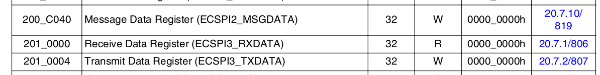
整个ecspi3的节点是在imx6ul.dtsi这个文件中的,可以看一下定义
 1 ecspi3: ecspi@02010000 {
 2     #address-cells = <1>;
 3     #size-cells = <0>;
 4     compatible = "fsl,imx6ul-ecspi", "fsl,imx51-ecspi";
 5     reg = <0x02010000 0x4000>;
 6     interrupts = <GIC_SPI 33 IRQ_TYPE_LEVEL_HIGH>;
 7     clocks = <&clks IMX6UL_CLK_ECSPI3>,
 8             <&clks IMX6UL_CLK_ECSPI3>;
 9     clock-names = "ipg", "per";
10     dmas = <&sdma 7 7 1>, <&sdma 8 7 2>;
11     dma-names = "rx", "tx";
12     status = "disabled";
13 };
其中寄存器地址0x02010000就是ECSPI3组的首地址。
我们要在开发板对应的设备树文件下添加新外设的信息
 1 /*新添加spi设备信息*/
 2 &ecspi3 {
 3     fsl,spi-num-chipselects = <1>;                                /*1个片选*/
 4     cs-gpio = <&gpio1 20 GPIO_ACTIVE_LOW>;                        /*软件片选 设备树要求是cs-gpios*/
 5     pinctrl-names = "default";
 6     pinctrl-0 = <&pinctrl_ecspi3>;
 7     status = "okay";
 8
 9     spidev0:icm20608@0 { /*后面@0的0表示SPI接到哪个硬件片选*/
10         reg= <0>;
11         compatible = "alientek,icm20608";
12         spi-max-frequency = <8000000>;    /*时钟频率,单位为Hz*/
13     };
14 };
新的外设一定要是在ecspi3这个节点下面的(有可能开发板的设备树文件里没有用到ecspi3,要自己手动添加)。然后新的设备就是spidev0,最后的@0是因为我们的ECSPI接口在硬件定义上可以接4个外设,通过硬件的片选信号去选择,0就表示第1个外设。其他就没什么可说的了其中我们可以参考文档中的信息对设备树文件进行编辑(Documentation/devicetree/bindings/spi/spi-bus.txt)。主要就是匹配的原则一定要和驱动文件中的内容一致。第4行的cs-gpio和文档里的说明是有区别的,文档中说的是cs-gpios,是配合spi_write和spi_read两个函数使用的,这里有一些问题我们回来再说。
修改好设备树文件以后可以启动开发板,可以看到/sys路径下的spi下有了新的设备
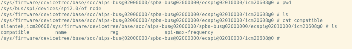
打印一下of_node里面的compatible,可以看到相关属性,说明SPI设备加载正常。再加载一下驱动基础框架
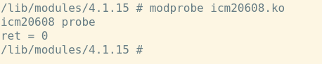
probe函数运行正常,说明驱动框架匹配的也没问题。下面我们主要完成字符设备的添加等功能。
字符设备添加
这个过程没什么可讲的,但是由于我们一直使用platform来构建驱动(特别是MISC杂项驱动,都是内核帮我们完成这个步骤),可能都忘的差不多了。所以要回顾一下
  1 /**
  2  * @file SPI框架.c
  3  * @author your name (you@domain.com)
  4  * @brief SPI设备完整框架
  5  * @version 0.1
  6  * @date 2022-09-24
  7  *
  8  * @copyright Copyright (c) 2022
  9  *
 10  */
 11 #include <linux/module.h>
 12 #include <linux/kernel.h>
 13 #include <linux/init.h>
 14 #include <linux/fs.h>
 15 #include <linux/uaccess.h>
 16 #include <linux/io.h>
 17 #include <linux/types.h>
 18 #include <linux/cdev.h>
 19 #include <linux/device.h>
 20 #include <linux/of.h>
 21 #include <linux/of_address.h>
 22 #include <linux/of_irq.h>
 23 #include <linux/gpio.h>
 24 #include <linux/of_gpio.h>
 25 #include <linux/irq.h>
 26 #include <linux/interrupt.h>
 27 #include <linux/input.h>
 28 #include <linux/spi/spi.h>
 29
 30
 31 #define ICM20608_CNT            1
 32 #define ICM20608_NAME           "icm20608"
 33
 34 /*设备结构体*/
 35 struct icm20608_device
 36 {
 37     int major;
 38     int minor;
 39     dev_t dev_id;
 40     struct cdev cdev;
 41     struct class *class;
 42     struct device *device;
 43     int cs_gpio;
 44
 45     void *private_data;
 46 };
 47
 48 struct icm20608_device icm20608_dev;
 49
 50 static int icm20608_open(struct inode *inode, struct file *file)
 51 {
 52     int ret = 0;
 53     return ret;
 54 }
 55
 56 /*读文件*/
 57 ssize_t icm20608_read(struct file *file, char __user *buf, size_t cnt, loff_t *off)
 58 {
 59     int ret = 0;
 60     return ret;
 61 }
 62
 63 /*关闭文件*/
 64 static int icm20608_release(struct inode *inode, struct file *file)
 65 {
 66     int ret = 0;
 67     return ret;
 68 }
 69
 70 /*文件操作集合*/
 71 struct file_operations icm20608_fops = {
 72     .owner = THIS_MODULE,
 73     .open = icm20608_open,
 74     .read = icm20608_read,
 75     .release = icm20608_release,
 76 };
 77
 78
 79 /*读多个寄存器*/
 80 static int icm20608_read_regs(struct icm20608_device *dev, u8 reg, u8 *buf, int len)
 81 {
 82     int ret = 0;
 83     return ret;
 84
 85 }
 86
 87 /*写多个寄存器*/
 88 static int icm20608_write_regs(struct icm20608_device *dev, u8 reg, u8 *buf,int len)
 89 {
 90     int ret = 0;
 91     return ret;
 92 }
 93
 94 /*读取单个寄存器*/
 95 static unsigned char icm20608_read_onereg(struct icm20608_device *dev, u8 reg)
 96 {
 97     u8 data = 0;
 98     return data;
 99 }
100 /*写单个寄存器*/
101 static void icm20608_write_onereg(struct icm20608_device *dev, u8 reg, u8 value)
102 {
103
104 }
105
106 /*icm20608外设初始化*/
107 void icm20608_device_init(struct icm20608_device *dev)
108 {
109
110 }
111
112
113 static int icm20608_probe(struct spi_device *spi)
114 {   int ret = 0;
115
116     /*申请字符设备号*/
117     icm20608_dev.major = 0;
118     if(icm20608_dev.major){
119         icm20608_dev.dev_id = MKDEV(icm20608_dev.major,0);
120         ret = register_chrdev_region(icm20608_dev.dev_id,ICM20608_CNT,ICM20608_NAME);
121     }
122     else{
123         ret = alloc_chrdev_region(&icm20608_dev.dev_id,0,ICM20608_CNT,ICM20608_NAME);
124         icm20608_dev.major = MAJOR(icm20608_dev.dev_id);
125         icm20608_dev.minor = MINOR(icm20608_dev.dev_id);
126     }
127
128     if(ret<0)
129     {
130         printk("icm20608 chrdev_region err\r\n");
131         goto fail_devid;
132     }
133     printk("icm20608 major=%d,minor=%d",icm20608_dev.major,icm20608_dev.minor);
134
135     /*添加字符设备*/
136     icm20608_dev.cdev.owner = THIS_MODULE;
137     cdev_init(&icm20608_dev.cdev,&icm20608_fops);
138     ret = cdev_add(&icm20608_dev.cdev,icm20608_dev.dev_id,ICM20608_CNT);
139     if(ret<0)
140     {
141         goto fail_cdev;
142     }
143     /*添加类*/
144     icm20608_dev.class = class_create(THIS_MODULE,ICM20608_NAME);
145     if(IS_ERR(icm20608_dev.class))
146     {
147         ret = PTR_ERR(icm20608_dev.class);
148         goto fail_class;
149     }
150
151     /*添加字符设备*/
152     icm20608_dev.device = device_create(icm20608_dev.class,NULL,
153                                         icm20608_dev.dev_id,NULL,ICM20608_NAME);
154     if(IS_ERR(icm20608_dev.device))
155     {
156         ret = PTR_ERR(icm20608_dev.device);
157         goto fail_device;
158     }
159
160
161     /*私有数据设置*/
162     icm20608_dev.private_data = spi;        //spi就是probe函数传进来的spi_device参数
163     return 0;
164
165 fail_device:
166     class_destroy(icm20608_dev.class);
167 fail_class:
168     cdev_del(&icm20608_dev.cdev);
169 fail_cdev:
170     unregister_chrdev_region(icm20608_dev.dev_id,ICM20608_CNT);
171 fail_devid:
172     return 0;
173 }
174
175 static int icm20608_remove(struct spi_device *spi)
176 {
177     int ret = 0;
178     /*释放资源*/
179     cdev_del(&icm20608_dev.cdev);
180     unregister_chrdev_region(icm20608_dev.dev_id,ICM20608_CNT);
181     device_destroy(icm20608_dev.class,icm20608_dev.dev_id);
182     class_destroy(icm20608_dev.class);
183     gpio_free(icm20608_dev.cs_gpio);
184     return 0;
185 }
186
187 static const struct of_device_id icm20608_of_match[] = {
188     {.compatible = "alientek,icm20608"},
189     {}
190 };
191
192 /*传统匹配*/
193 static const struct spi_device_id icm20608_id[] = {
194     {"alientek,icm20608",0},
195     {}
196 };
197
198 struct spi_driver icm20608_driver = {
199     .driver = {
200         .name = "icm20608",
201         .owner = THIS_MODULE,
202         .of_match_table = icm20608_of_match,
203     },
204     .probe = icm20608_probe,
205     .remove = icm20608_remove,
206     .id_table = icm20608_id,
207 };
208
209
210 static int __init icm20608_init(void)
211 {
212     int ret = 0;
213     ret = spi_register_driver(&icm20608_driver);
214     printk("ret = %d\r\n",ret);
215     return ret;
216 }
217
218 static void __exit icm20608_exit(void)
219 {
220     spi_unregister_driver(&icm20608_driver);
221 }
222
223 module_init(icm20608_init);
224 module_exit(icm20608_exit);
225 MODULE_LICENSE("GPL");
226 MODULE_AUTHOR("AC");
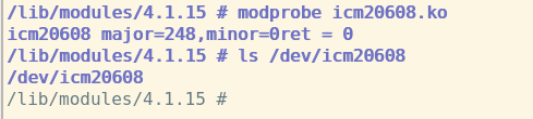
并且在上面的代码中还预留了SPI的读写、设备初始化等代码,在后面我们只需要完善各个功能对应的函数就可以了。可以把完成的框架make以后加载一下,可以看到/dev下的设备节点
截止到现在为止,我们几乎没有涉及到新的知识点,但是下面就要开始做SPI的读写函数了。
SPI读写函数
SPI的读写函数其实在spi/spi.h文件里是有内核已经完成的,但是我们先自己写一个能更好的知道这个通讯的流程。因为每个外设的SPI写或读的流程可能会有一些差异,对icm20608来说,因为该IC同时支持I2C和SPI,如果使用SPI读写寄存器是需要吧寄存器的地址位的最高位置一,写的话寄存器地址最高位置零,剩下的7个bit才是寄存器的实际地址。所以这里要注意一下处理方法。
SPI设备数据收发流程
前面说了,SPI设备驱动的核心是spi_driver,在向Linux内核注册spi_driver成功以后,我们就可以使用SPI核心层的API来进行SPI外设的读写操作了。这里要用到一个spi_transfer的结构体
 1 struct spi_transfer {
 2     /* it's ok if tx_buf == rx_buf (right?)
 3      * for MicroWire, one buffer must be null
 4      * buffers must work with dma_*map_single() calls, unless
 5      *   spi_message.is_dma_mapped reports a pre-existing mapping
 6      */
 7     const void    *tx_buf;
 8     void        *rx_buf;
 9     unsigned    len;
10
11     dma_addr_t    tx_dma;
12     dma_addr_t    rx_dma;
13     struct sg_table tx_sg;
14     struct sg_table rx_sg;
15
16     unsigned    cs_change:1;
17     unsigned    tx_nbits:3;
18     unsigned    rx_nbits:3;
19 #define    SPI_NBITS_SINGLE    0x01 /* 1bit transfer */
20 #define    SPI_NBITS_DUAL        0x02 /* 2bits transfer */
21 #define    SPI_NBITS_QUAD        0x04 /* 4bits transfer */
22     u8        bits_per_word;
23     u16        delay_usecs;
24     u32        speed_hz;
25
26     struct list_head transfer_list;
27 };
其中tx_buf里保存的是要发送的数据,而rx_buf里是要接受的数据,len时要进行传输的数据长度。和I2C不同,SPI是一种全双工的通讯,所以在没测通讯的过程中收发的字节数应该是一样的。所以这个len就没有接收或发送的区别。在设置好这个spi_transfer对象以后,要把这个spi_transfer对象封装到另外一个spi_message结构体里
 1 struct spi_message {
 2     struct list_head    transfers;
 3
 4     struct spi_device    *spi;
 5
 6     unsigned        is_dma_mapped:1;
 7
 8     /* REVISIT:  we might want a flag affecting the behavior of the
 9      * last transfer ... allowing things like "read 16 bit length L"
10      * immediately followed by "read L bytes".  Basically imposing
11      * a specific message scheduling algorithm.
12      *
13      * Some controller drivers (message-at-a-time queue processing)
14      * could provide that as their default scheduling algorithm.  But
15      * others (with multi-message pipelines) could need a flag to
16      * tell them about such special cases.
17      */
18
19     /* completion is reported through a callback */
20     void            (*complete)(void *context);
21     void            *context;
22     unsigned        frame_length;
23     unsigned        actual_length;
24     int            status;
25
26     /* for optional use by whatever driver currently owns the
27      * spi_message ...  between calls to spi_async and then later
28      * complete(), that's the spi_master controller driver.
29      */
30     struct list_head    queue;
31     void            *state;
32 };
我们要用到的就是spi_message里的transfer成员。但是spi_message在使用前需要初始化,并且封装spi_transfer的过程以及发送数据的过程需要用到几个函数。下面我们看下这几个函数
spi_message初始化
spi_message在声明以后需要进行初始化
1 static inline void spi_message_init(struct spi_message *m)
2 {
3     memset(m, 0, sizeof *m);
4     INIT_LIST_HEAD(&m->transfers);
5 }
直接把声明好的message传进来就行了。
spi_transfer封装
在完成了spi_transfer的构建和message初始化以后就可以进行封装了。所用函数如下
1 static inline void
2 spi_message_add_tail(struct spi_transfer *t, struct spi_message *m)
3 {
4     list_add_tail(&t->transfer_list, &m->transfers);
5 }
函数的参数分别是transfer对象和message对象。
传输数据
数据传输分同步和异步,使用异步传输时程序不会阻塞在SPI通讯时,但是需要设置spi_message里的complete成员(上面代码第20行),complete成员是一个回调函数,在完成了SPI传输以后会直接调用这个函数,异步传输所用的函数如下
extern int spi_async(struct spi_device *spi, struct spi_message *message);
函数参数直接就能看明白。
同步传输时程序会阻塞在通讯的过程,但是由于我们这里通讯的过程很短暂,可以先不考虑这个阻塞导致的消耗,在这个SPI驱动的架构我们就是用同步传输的模式,需要用到下面的函数
extern int spi_sync(struct spi_device *spi, struct spi_message *message);
上面就是SPI进行数据传输主要使用的几个函数,下面我们来完成SPI的读写函数
读函数
首先是读函数
 1 /**
 2  * @brief SPI读连续寄存器
 3  *
 4  * @param dev SPI外设结构体
 5  * @param reg 读取首个寄存器地址
 6  * @param buf 读取数据存放缓存
 7  * @param len 读取寄存器长度
 8  * @return int
 9  */
10 static int icm20608_read_regs(struct icm20608_device *dev, u8 reg, void *buf, int len)
11 {
12     int ret = 0;
13     struct spi_device *spi = (struct spi_device *)dev->private_data;    //私有数据
14
15     unsigned char txdata[1];                       //发送数据
16     unsigned char * rxdata;                        //接收数据缓存
17     struct spi_message msg;                        //spi_message
18     struct spi_transfer *t;                        //spi_transfer
19
20     /*拉低片选*/
21     gpio_set_value(dev->cs_gpio,0);
22
23     /*申请内存*/
24     t = kzalloc(sizeof(struct spi_transfer), GFP_KERNEL);
25     rxdata = kzalloc(sizeof(char) * len, GFP_KERNEL);
26
27     txdata[0] = reg | 0x80;          //地址最高位置一
28     t->tx_buf = txdata;              //发送数据(寄存器地址)
29     t->rx_buf = rxdata;              //接收数据
30     t->len = len + 1;                //数据长度,第一帧为地址,所以要加1
31
32     spi_message_init(&msg);          //message初始化
33     spi_message_add_tail(t,&msg);    //transfer封装
34     ret = spi_sync(spi,&msg);        //传输
35
36     /*将读取到的数据复制给buf*/
37     memcpy(buf , rxdata+1, len);    //rxdata为指针,+1是只要读取的数据
38
39     /*释放内存*/
40     kfree(t);
41     kfree(rxdata);
42     /*拉高片选*/
43     gpio_set_value(dev->cs_gpio,1);
44     return ret;
45 }
在上面的的操作中,我们使用了手动拉低GPIO的方式来控制片选信号。首先先声明了message和transfer,还有发送和接受的缓存txdata和rxdata。因为最终我们要的是这个rxdata中的一部分(除去第一个元素),所以要对其申请一段内存;还有transfer也要有一段内存与其对应,所以要用到kzalloc申请内存。因为是全双工通讯,首先向外设发送写入数据寄存器的地址,读取数据的时候要把读取到的第一个byte的数据删掉。所以我们定义的接收数据的缓存是个指针变量,在第37行从内存复制数的时候指针加了1,自动删除了第一个元素。同理,由于第一帧数据时发送的地址,我们读n个字节数据时其实实际上是通讯录n+1个字节的数据。
写数据